Tuesday, October 6, 2015

ISP Header Adapter

So Having knowledge of circuit design doesn't have to be limited to huge complex boards.  Some times a simple board is just as handy. I use the 6pin ICSP header for my AVR designs, So all the boards I use. Or even look at. It's small, has just what is needed and when I finally build a programmer pen. Unfortunatly most programmer designs are based on the 10 pin design. I wish that the 10 pin standard was designed so that the 6pin was a sub set. Seriously awesome if all you needed was a different end on a ribbon cable.

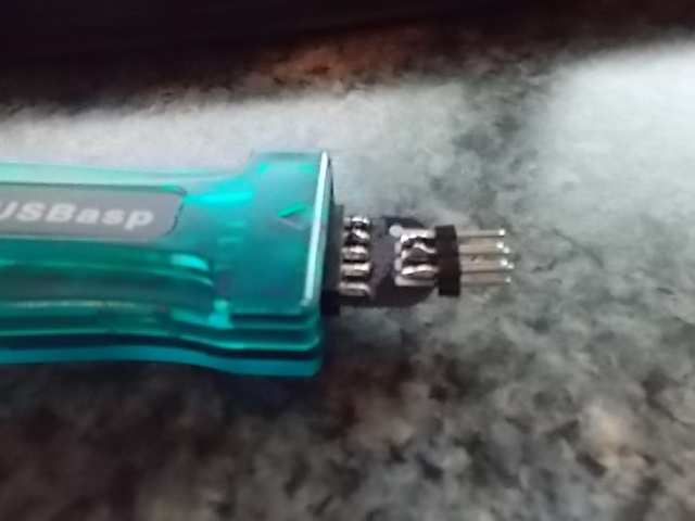
I was on that Evil Beacon of Avarice(or EBAY) known the world over looking for cheep parts like headers, jumpers and the like. I generally like to look for a source and then see what they sell. most seem to either have a few odds and ends or everything under the sun. The seller in question had just about everything I wanted at the time and a USBASP programmer with a case for all of $4. It's has 10 pins and I have nothing with 10 pins.

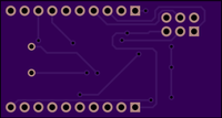
Looking around e-bay the solution was a ugly adapter for the destination board. Long slender things that stick up in the air unsupported. That's just asking for mangled pins and the like. And it looks bad in pictures. I changed the concept to the opposite. I adapted the 10 pin header to use a 6 pin cable. My first batch is great. I had to test it with my USB Tiny ISP since that cheep 4 dollar programmer has some issues. Yeah more on that in the next post. This has the added benefit of being able to use a 6 pin programmer with a 10 pin board.


This is version 1. The next version will end up larger. I'm going to use a header design to fit in the keyed IDC socket, Then use a keyed 2x3 socket for the top. Sugru or polymorph for a bit of covering. The goal would be to make it more stable and a bit more foolproof. 


Saturday, September 19, 2015

Arduino as ISP Shield

When I started playing with AVRs I started like most people. I bought an Arduino starter kit, then added on. And then added some more. Quickly I realized that a lot of projects need far less then an a $30 boards potential. So the Tiny series was a beautiful discovery. They're popular that's for sure. 

I have a USB Tiny ISP from adafruit that I love because i got to assemble it. I mounted a small breadboard to it and it works great. But it likes to slid around. I do have 3 Arduinos mounted to plexiglass plates with half size bread boards. The make great programmers for the tiny AVRs. They take a bit of time to set up. Since I've started using OSHPark making custom boards is obtainable. They also have a large user contributed project section a but of searching found the Pixie85, Pixie2313 and Pixie84 boards. These simply add an ISP header to the chips. Brilliant. I added chip sockets and boom easy to swap out a chip. That solved the messy breakouts with the USBtinyISP. 
My solution to the Arduino setup issue was a custom shield. Searching arduino isp on OSHPark came up with solutions the had sockets for only a certain chip, or were just clumsy to use. I liked Arno's Tiny ISP shield but the chip socket was a deal breaker. So I set about making my own.

Mistakes happen when designing circuit boards. Sparkfun has made a few interesting mistakes on boards. This one had two mistakes, one being a "unintended feature" that I might keep. This is Rev 0.2 because the first version I some how added a 2x3 header with 2mm pin spacing that was caught before I submitted to fab.  The Second issue is easily seen in the completion photo. I miss counted the offset of the headers. The holes for the headers were loose enough to allow a slight angle. So my design is  .07 inches less wide that it should be. It saves 20 cents a board and nothing is stressed but the angle. it sides on perfectly since I soldered the headers in while attached to the Arduino. My test board didn't need the cap, matter of fact it hindered operation and wouldn't allow the Arduino to work. The LED's are designed to be optional. the wires come from under, The holes need to be slightly bigger, a 22(7) wire was too big, I had to remove a strand to get them to fit.

Version 0.3 is slated to have the extra 0.07 inches in width, and the right most led will get a header pin.


Friday, August 28, 2015

Eagle Cad Files to Dip Trace

I've fallen in love with Dip Trace. I find it so much faster to use. Unfortunately Eagle is the standard, so I still have to have it installed. I find myself wishing to edit designs that are in Eagle in Dip Trace because Dip Trace is intuitive, and it spits out Gerbers and NC Drills without any setup. There is hope.

Dip Trace comes with a couple of Eagle ULPs that will Convert eagle files to Dip Trace ASCII files that can be imported. I'm looking for a new ICSP that uses 6 pins. but all the sleek ones use the 10 pin headers, or are huge. So A trip to OSH Park and a search for ICSP and we find µUSBasp. the download link is an Eagle file so grap it, and load it into Eagle...


In the file menu there is a "Run ULP..." Item click on it.


Next an open file box opens, find the Dip Trace install folder. Mine was in C:\Program Files (x86)\
in there is a Utils folder. Open that and run Eagle_to_DipTrace_PCB.ulp

Next is a save file dialog. Save the file with a .asc extention. YOU NEED TO USE .asc AT THE END OF THE FILE NAME. not doing so will cause DipTrace to not see the file, so you have to find in in Explorer and rename it. 

Notice the little finish message at the bottom. That's it no frills. 

in a new Dip Trace PCB file, go into the file menu select import and Select DipTrace ASCII. Find your .asc file and open it.


Notice there isn't all the fanciness. board outline is broken, and all the text is missing. The labels are huge. Clean up takes only a few minutes. I generally hide the labels so I'm not concerned, I have the file and schematics so part ID's aren't needed. Everything is in it's place.


Just one more reason to love DipTrace, 

Tuesday, August 25, 2015

Arduino ISP

*** UPDATE ***
I mistakenly added the wrong 2x3 header. It's not a 0.1" spacing. I've corrected it and added a few LED's that you can wire up as per the Arduino ISP sketch. look for v0.2 on the board.
***End UPDATE

Completed, write up here.

For programing tiny 85 and 84 with Arduino, read the high low tech article it'll get you there fast.

Most people I imagine start with playing with AVRs via the Arduino community. Unfortunately moving from your easy to use Arduino to a bare chip isn't easy. It requires a programmer, and those can be as little as a couple of dollars on ebay for a usbtinyisp or avrisp clone. I have a nifty Arduino with breadboard mounted on a piece of Plexiglas that is great for attiny development, especially using attiny85's since the Arduino has power, and I can use it as programmer. Most starter kits come with similar setups, so alot of people have them. It's a pain to setup, and the more wires the more chances to fail miserably. and disconnecting to rapidly test is a little painful.

For the chip side of things I've ordered a few pixie85's and pixie2313 boards. so I'll have the ICSP header broken out. Adafruit has a ICSP breadboard adapter and a 6" 2x3 idc cable... for all of 3 bucks for the set. You'll need some thing similar.

Scouring the internet the solution to my woes seemed to hack a 6 pin IDC cable to use the arduinoISP and an ICSP connector. Sound good but still one of those what pins do I use moment. Adding to the complexity the UNO requires you to disable the auto reset for the serial. This requires a 10uf cap between reset and gnd. Way too much to remember every time. 

The solution is obviously a shield. Unfortunately all the ones I've found already designed are for chip sockets. and we fairly expensive for what i wanted, a cheep, easy to setup programmer board that I could give away.

So the next installment in PCB Design is the ArduinoISP header shield. The LED's are optional, they hook up with wire from "D7-D9" on the back of the board. That gives activity, error, and heartbeat. It didn't add to the price so why not. Also it the cutout on the right so that pin 9 should be exposed.

These are being ordered next week some time. So figure at the end of september I should have them tested.


A simple square inch design that straddles the arduino. I finished the design today. for the uno you need a cap. older boards might need a 120 ohm resistor, though the cap might work too.

It's a bout 5 bucks for the 3 boards. Cheap enough to give away at parties.

Monday, August 24, 2015

Memory

I've played with Arduinos for a while. The IDE is functional. The API has a really heavy abstraction. That really becomes problematic when you want to start using the ATTINY processors. Lets look at the popular AVRs
FlashRamEEPROM
tiny 23132K128B128B
tiny 84 4K512B512B
tiny 85 8K512B512B
mega 32832KB2k1k

The mega 328 has enough ram to use it carelessly. It's flash size is huge. translating a basic Arduino program into a tiny2313 might be a little challenging. So lets go over a few memory tricks worth mentioning. today we're still going to be using an Arduino as a target since I have one here and most people will too.

Data types int and char are very different beasts. Char is an integer type guaranteed to be 8 bits in size, int is 16bits. so a char is 1 byte, where as an int is 2 bytes. In general, use char when you can. unsigned it'll hold numbers 127 to -126, unsigned will get you 0-255. a trick that helps at least me is declaring the following at the top of my program: unless you need to go larger, chars will make that 128 bytes last a little longer.

Macros are the next bit of memory stretching arduino doesn't teach. if you have unchanging data, or constants, a define is better than a variable. take the following:

#define NUM_PINS 4
int num_pins 4;

The first line will insert a 4 anywhere the compiler sees NUM_PINS. This allows for centralized information without using ram to do it. The second line uses 16 bits to sore 3 bits of data. a char, or unsigned char is better fit, since it only uses 8 bits.

These are basic C items that you can use in the standard Arduino stuff. To get in the habit.

Lets revamp the fade code from the arduino examples a bit. The original uses 15 bytes of memory. the bare example uses 9, so those 6 bytes are from the 3 variables. This one does it in 12 bytes.

/*
 Fade

 This example shows how to fade an LED on pin 9
 using the analogWrite() function.

 This example code is in the public domain.
 */

#define LED 9;           // the pin that the LED is attached to
unsigned char fadeAmount 10;    // how many points to fade the LED by

unsigned char brightness = 0;    // how bright the LED is we need 0 to 255

// the setup routine runs once when you press reset:
void setup() {
  // declare pin 9 to be an output:
  pinMode(LED, OUTPUT);
}

// the loop routine runs over and over again forever:
void loop() {
  // set the brightness of pin 9:
  analogWrite(LED, brightness);

  // change the brightness for next time through the loop:
  brightness = brightness + fadeAmount;

  // reverse the direction of the fading at the ends of the fade:
  if (brightness == 0 || brightness == 255) {
    fadeAmount = -fadeAmount ;
  }

  // wait for 30 milliseconds to see the dimming effect
  delay(30);
}

Sunday, August 23, 2015

OSH park buys

I bought some more boards off of OSH Park. I found them helpful. Only one was my own, and that was based off of another I found but it was very big and big costs money.

LED Simple

My design but I was inspired by Greg's LED board. For a beginner or for teaching that is a better board. It allows visualization. But at 5 bucks a piece someone that has a little more understanding of electronics might like to spend less and get a little more bang.

I have a friend trying to get into micro controllers and these short cut boards can be the difference between learning or tossing a bread board across the room. I also wanted to use these on the edge of a bread board connected directly to either a 74595 or Port D of a tiny 2313/4314. So I added 2 ground pads in the upper corners so i don't have to populate the ground pad. It was a 10 minute board, the routing could be better. These are cheep, so I'm defiantly going to revise this a bit more maybe do the resistors vertical next to the header. the header is going to be slimmed down to 8 pins, the "floating" ground pin makes more sense to me, for versatility. A 4 Led version would be nice too. Also i can see a female header and rubber feet being a good fit as well.


The other boards:
Pixie85 and Pixie2313 Just simply icsp jacks with attached chips. Removes one step and a lot of little wires. That's a win win.

Sturdy Pot Adapter. Simply a briliant way to add a big pot to a bread board. I have huge fingers. I bought 9. that were 1.80 for 3. Simply awesome, every starter kit needs these. 

Saturday, August 22, 2015

Firsts

I've started to get back into my highly technical side of life again. The first step is to learn more about AVR's Sure that arduino sitting on you desk is cool and all and those wires in that breadboard impress people. But when you start making real projects that you want to keep you need to do something more than put that breadboard in a box.

This is a board based on a ATTINY 2313/4313. It's very SMD, but designed for hand soldering. It's 7 breadboard rows wide(0.7 inches between the 10 pin headers) so it'll fit well. and you can solder wires when you need to make a real project, way more street cred hand soldering 0805's then 1/4 watt TH resistors.

Why a tiny 4313 when 2313's are so popular? Double the memory and they are still under 2 bucks each. I also want to play with VUSB it takes up most of the 2313's flash space. USB circuits are integrated, and not broken out to the bread board. Usb provides easy power and some real functionality. To round it off, I'll add a spot for a crystal. These have been sent to OSH Park for building. Set me back $15 for 6. I've started using DIP Trace for PCB stuff. It's faster than eagle, and parts building is less complicated. I've included gerber and dip trace files. The drawing is unfinished. I like to connect headers on the PCB vs line drawings. this makes sure i get the right pins. Unfortunately I haven't figured out how to get the PCB view back in to the drawings. but the PCB file is correct, and you can work it from there.

The row of discrete components are top to bottom: 100k ohm, 68 ohm, diode, diode, 68 ohm, 1.5K ohm

A31727CT-NDCONN MINI USB RCPT RA TYPE B SMD1
ATTINY4313-SU-NDIC MCU 8BIT 4KB FLASH 20SOIC1
CTX904-NDCRYSTAL 12.0000MHZ 18PF T/H1
MMSZ4685-TPMSCT-NDDIODE ZENER 3.6V 500MW SOD1232
311-68ARCT-NDRES SMD 68 OHM 5% 1/8W 08052
311-1.5KARCT-NDRES SMD 1.5K OHM 5% 1/8W 08051
311-100KCRCT-NDRES SMD 100K OHM 1% 1/8W 08051
445-1273-1-NDCAP CER 22PF 50V 5% C0G 06032


Everything was ordered today so check back in a couple of weeks when OSH Park cranks them out.